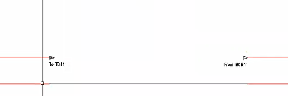
We use the source and destination arrows to identify wire networks in a wiring diagram. When we start panel test or FAT/SAT (Factory Acceptance Test/Site Acceptance Test) it is very important to mention wire destination and source arrows so that wiring can be easily understood and any modification required in wiring connections can be done easily.
Let see how we can insert destination and source arrows in the wiring diagram in AutoCAD Electrical.
1. Insert Source Arrow
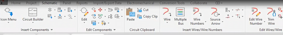
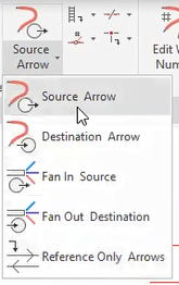
Click Schematic tab  Insert Wires/Wire Numbers panel Source Arrow drop-down.
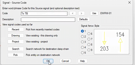
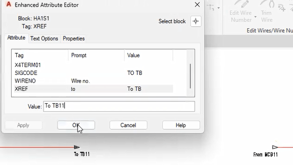
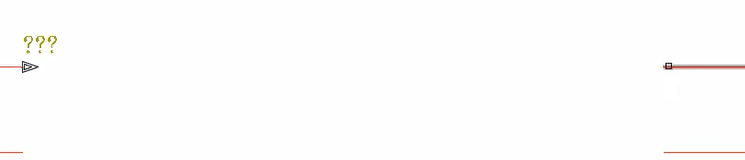
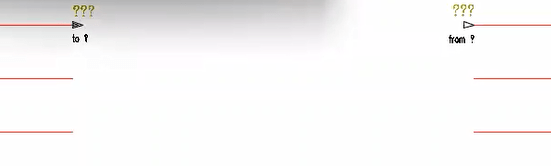
 ![]() Click on Source Arrow Select the wire end Put the value of code in “signal -source cade” Ok Click on inserted source arrow Enhanced attribute Editor (Put the value in XREF ( Exp. To TB11) and WireNO ) OK
Click on Source Arrow Select the wire end Put the value of code in “signal -source cade” Ok Click on inserted source arrow Enhanced attribute Editor (Put the value in XREF ( Exp. To TB11) and WireNO ) OK
2. Insert Destination Arrow
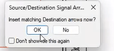
After inserted Source Arrow One dialog box will come (Insert matching Destination arrow now ) Click OK Select the wire first point Click on inserted destination arrow Enhanced attribute Editor (Put the value in XREF (Exp From MCB11) and WireNO ) OK
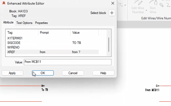
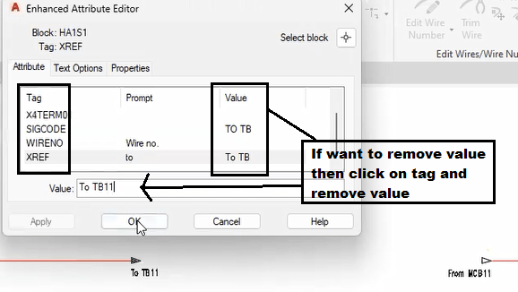
Note :- If you want to remove the value from the tag then select the tag and remove the value or if you want to keep the tag then keep the value in the tag.
Leave a Reply