A smart plug with energy monitoring is an electrical outlet adapter that connects to your standard power socket and allows you to control and monitor any device plugged into it via a smartphone app or voice assistant (compatible with Google Assistant, Alexa, etc.). What sets these smart plugs apart is their built-in energy monitoring feature, which tracks and displays real-time and historical energy consumption data for the connected device.
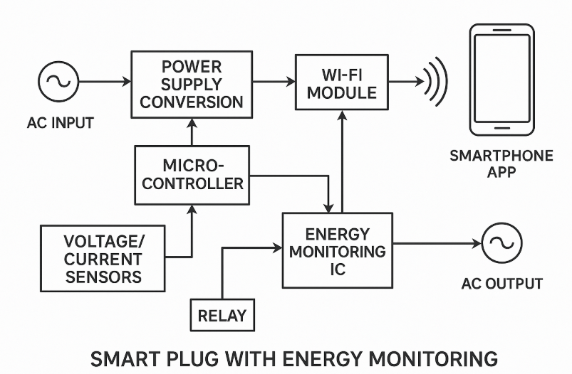
Detailed Component Breakdown and Signal Flow
Power Supply Section
The smart plug begins with AC mains input (typically 110-240V AC) that feeds into two parallel paths:
- Energy monitoring path: Voltage divider network reduces 250V to 0-5V for safe measurement by the ADC
- Power conversion path: AC-to-DC converter (often using flyback topology with controllers like VIPer16) converts mains voltage to regulated DC voltages
The power supply generates multiple voltage rails:
- 5V DC: Powers the relay and higher current circuits
- 3.3V DC: Powers the microcontroller, WiFi module, and digital circuits (converted from 5V using LDO regulator)
- -12V DC: Used for relay and TRIAC gate drive (in some designs)
Energy Monitoring Circuit
The energy monitoring section consists of specialized components for precise measurement:
Voltage Sensing:
- High-precision resistive voltage divider network (typically 25 ppm accuracy)
- Signal conditioning to scale 0-250V AC to 0-5V for ADC input
- 24-bit Sigma-Delta ADC for high-resolution voltage measurement
Current Sensing:
- Current transformer (CT) or precision shunt resistor (typically 5mΩ, 25 ppm)
- For CT: Burden resistor converts current to voltage signal
- For shunt: Direct voltage measurement across the resistor
- 24-bit Sigma-Delta ADC for current measurement
Energy Monitoring IC:
Popular ICs include STPM10, HLW8012, ADE7753, or BL0937. These specialized chips:
- Calculate real-time power (P = V × I × cos φ)
- Measure both active and reactive power
- Perform energy integration over time
- Provide calibrated output with <0.1% accuracy
Microcontroller and Processing
The heart of the system is typically a WiFi-enabled microcontroller:
- ESP8266/ESP32: Most common, integrated WiFi capability
- STM32W108CB: With separate WiFi module
- MKM14Z64: ARM Cortex-M0+ based solution
Functions performed:
- Read energy monitoring data via SPI/I2C
- Process and calculate power/energy consumption
- Handle WiFi communication protocols (HTTP/MQTT)
- Control relay switching logic
- Manage scheduling and automation
Control and Switching Circuit
- Electromechanical relay: Primary switching element (typically 10-16A rating)
- TRIAC (optional): For soft-start/stop or dimming functions (T2035H in some designs)
- Relay driver: Protection and isolation (ULN2003 or similar)
- Optocouplers: Electrical isolation between control and high-voltage circuits
Communication Interface
- Integrated or external WiFi transceiver (2.4GHz band)
- Antenna (PCB trace or external wire antenna)
- Communication protocols: TCP/IP, HTTP, MQTT
- Security: WPA2/WPA3 encryption, AES-128 in some implementations
Data Transmission Flow:
- Sensor data → Microcontroller → WiFi module
- WiFi module → Home network → Internet/Cloud
- Cloud service → Mobile app
- Mobile app → Cloud → WiFi module → Microcontroller → Relay control
Safety and Protection Circuits
Critical safety features include:
- Fuse protection: Primary overcurrent protection
- MOV (Metal Oxide Varistor): Surge protection
- Optocoupler isolation: Between low-voltage control and high-voltage switching
- Thermal protection: Automatic shutdown on overheating
- Current limiting: Prevents damage from overcurrent conditions
User Interface Elements
- Status LEDs: Power, WiFi connection, relay state indicators
- Push buttons: Reset, WiFi pairing, manual control
- Mobile app interface: Real-time monitoring, control, scheduling, energy reports
Data Processing and Analytics
The microcontroller performs continuous calculations:
- Instantaneous power: P = V × I × cos(φ)
- Energy consumption: Integration of power over time (kWh)
- Power factor calculation: cos(φ) for reactive power analysis
- Historical data logging: Stored locally or in cloud
- Threshold monitoring: Automatic alerts for abnormal consumption
This technical implementation allows the smart plug to provide precise energy monitoring while maintaining safe, reliable remote control capabilities through a user-friendly smartphone interface.
Leave a Reply