Network interconnection drawings are essential documents in the fields of electrical and instrumentation engineering. They visually represent how various devices, panels, and systems are interconnected, ensuring clarity during installation, troubleshooting, and maintenance. This guide will help you understand the importance, components, and best practices for creating effective network interconnection drawings.
What is a Network Interconnection Drawing?
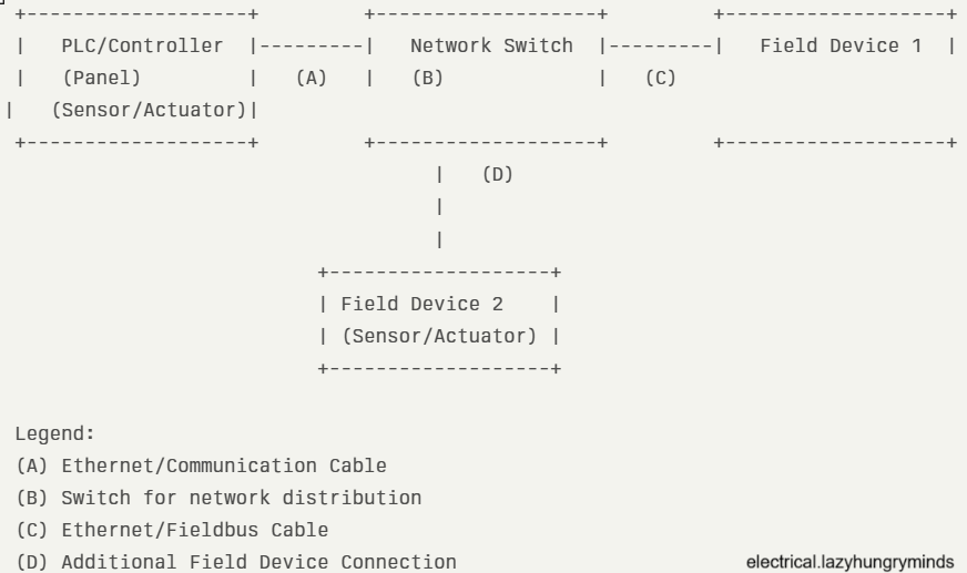
A network interconnection drawing (NID) is a schematic diagram that shows the physical and logical connections between different electrical and instrumentation devices within a facility. These drawings help engineers and technicians visualize how signals, power, and data travel between components such as PLCs, sensors, control panels, and field instruments.
Importance of Network Interconnection Drawings
- Clarity in Installation: Provides installers with a clear roadmap for wiring and device connections.
- Efficient Troubleshooting: Simplifies fault-finding by showing all interconnections at a glance.
- Documentation Compliance: Meets industry standards and client requirements for project documentation.
- Improved Communication: Ensures all stakeholders understand the system layout, reducing errors and misunderstandings.
Key Components of a Network Interconnection Drawing
- Device Symbols: Standardized symbols for PLCs, switches, relays, sensors, and other components.
- Connection Lines: Indicate wiring or network cables between devices.
- Labeling: Clear tags for cables, terminals, and devices for easy identification.
- Reference Numbers: Cross-references to other drawings such as wiring diagrams, loop diagrams, and P&IDs.
- Legend and Notes: Explains symbols, abbreviations, and any special instructions.
Steps to Create an Effective Network Interconnection Drawing
- Gather Project Information
- Collect all relevant documents: P&IDs, loop diagrams, cable schedules, and equipment lists.
- Identify Devices and Networks
- List all devices to be interconnected, including controllers, field instruments, and network switches.
- Choose the Right Drawing Software
- Use CAD tools or specialized electrical design software for accuracy and standardization.
- Draw Device Symbols and Layout
- Place device symbols logically, grouping related devices together.
- Connect Devices
- Draw lines representing cables or network connections, ensuring clarity and avoiding overlaps.
- Label Everything
- Assign unique identifiers to cables, terminals, and devices.
- Add Legends and Notes
- Include a legend for symbols and any special notes for installers or operators.
- Review and Verify
- Cross-check with other project documents and perform a peer review to ensure accuracy.
Best Practices for Network Interconnection Drawings
- Use internationally recognized symbols (such as IEC or ANSI standards).
- Keep the layout clean and uncluttered.
- Use color coding if possible for different types of signals (power, control, communication).
- Update drawings promptly when changes occur in the field.
- Store drawings in easily accessible digital formats for future reference.
Common Mistakes to Avoid
- Overcrowding the drawing with too many details.
- Omitting cable or terminal numbers.
- Using inconsistent symbols or labeling.
- Failing to update revisions after field changes.
Leave a Reply